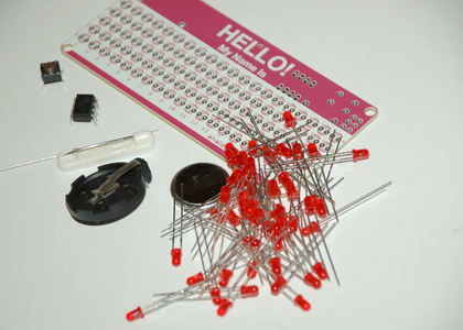
This is a pretty simple through-hole soldering kit. There are a lot of LEDs which can be a little tedious, but otherwise there are only a few other parts.
If it's your first time soldering, don't worry, soldering is easy! Before starting though, it would be helpful to read the Soldering is Easy comic book. This kit assumes you've read the comic.
To build this kit, you will need:
- soldering iron
- wire cutters
These instructions will go one LED at a time, but if you are using your own layout or unsure about the fit, it will be helpful to place all the LEDS in the board to test the layout.
Also make sure to check out the grid setting in the name layout tool. The board is sub-divided into 5 grids. If you want to be able to control individual letters, make sure to align them in the grid.
|
Parts List:
|
|
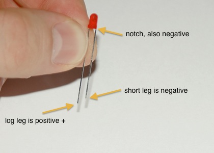
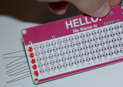
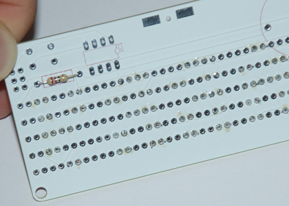
First, let's start with the LEDs. If you haven't already, check out the name layout tool to help you plan out your message. LEDs only work in a certain direction. The long lead is positive (+), the short lead is negative (-). There's also a notch taken out of the negative side, so you can tell if the leads are cut. On the PCB, all of the LEDs go the same way. There's a marking for the positive lead. Also a slight notch on the negative side in the silkscreen. |
|
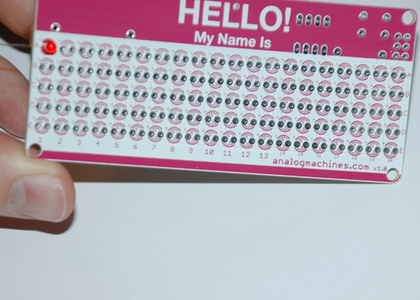
These instructions will go one LED at a time, but if you are using your own layout or unsure about the fit, it will be helpful to place all the LEDS in the board to test the layout. Also make sure to check out the grid setting in the name layout tool. The board is sub-divided into 5 grids. If you want to be able to control individual letters, make sure to align them in the grid. Place your first LED according to your layout. |
|
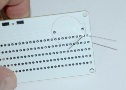
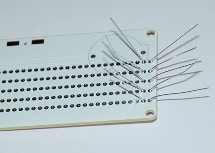
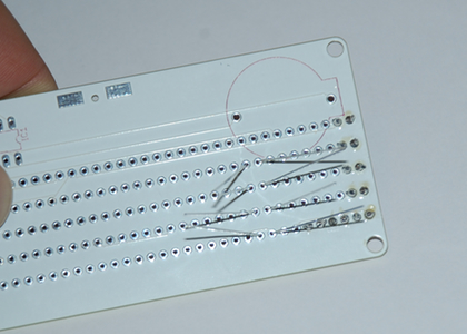
It's helpful to bend the leads 45 degrees so the LED will stay in while you turn the board over to solder. Solder the LED. |
|
You can continue soldering an LED at a time, or do a few in one go. I like to solder a column at a time. |
|
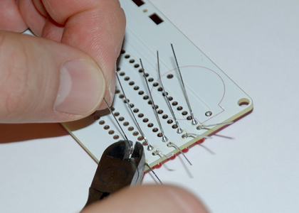
Once you have a set of LEDs soldered in, clip their leads to make it easier to continue. Safety tip!: hold the leads while you are cutting them! Otherwise they can fly out and hit you or others. |
|
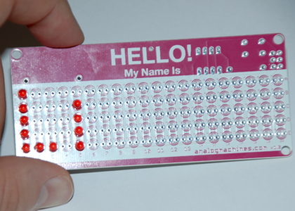
Continue on to the next letter. |
|
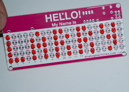
Continue until your name is finished. |
|
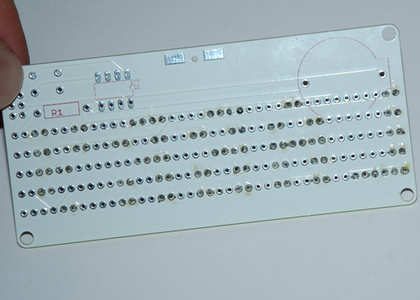
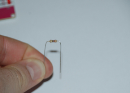
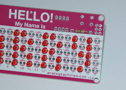
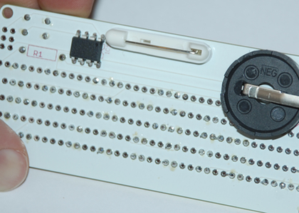
Next, let's put in the resistor. It's helpful to bend the leads first. Unlike LEDs, resistors work in either direction. The location for the resistor is marked on the back of the board (R1), but if you like you can also put it on the front of the board for some extra style. |
|
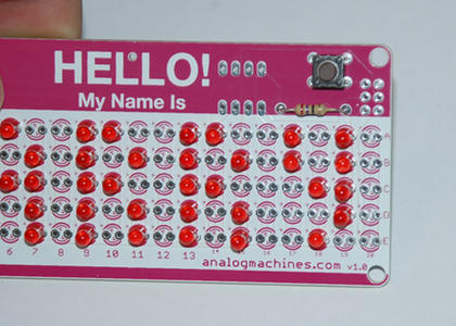
Next, let's solder the button. It goes on the front of the board and only fits one way. Be careful when you snap it through to not have your fingers directly behind it (the leads are sharp). |
|
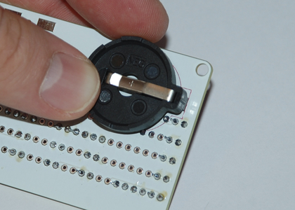
Next, let's add the battery holder. Align it to the shape on the board and solder on the other side. |
|
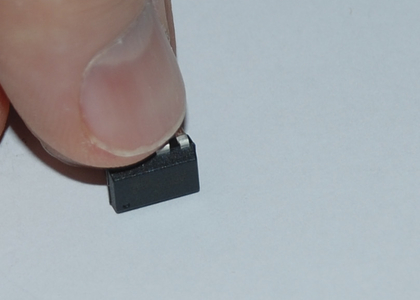
Next, let's add the microcontroller. The leads are usually bent out a little, you will want to straighten them before adding to the board. If you put the entire side down against a table and gently push, you can straighten all the legs at once. Repeat for the other side. |
|
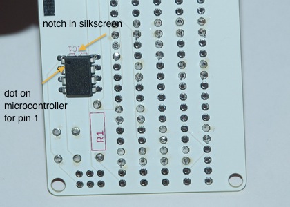
The microntroller needs to go in a certain way, or it won't work! The silkscreen has a notch in it to show where the top of the microcontroller should line up. The microcontroller has a dot that shows where pin 1 is. Line this up at the top closest to the notch in the silkscreen. |
|
The pinback is self-adhesive and doesn't require any soldering. Just take off the backing and push it into the board. The boards also have some mounting holes if you'd like to mount them somewhere, as well as pads at the top back for soldering something to them. |
|
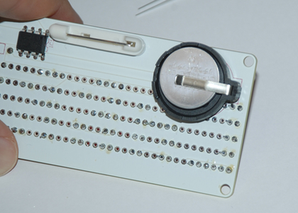
Okay, just add the battery! The positive side faces up. |
|
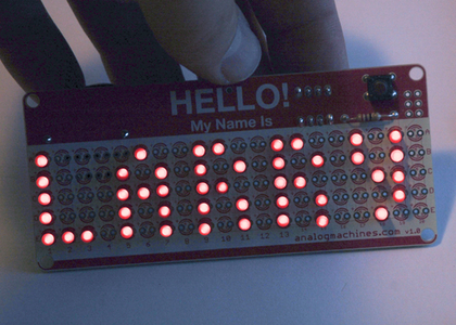
That's it! Your board should now be running! |